Sizes in Stock
1/2″NB TO 60″NB
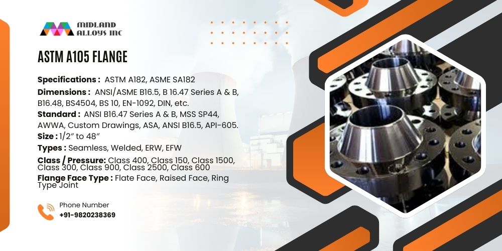
Standard
ASTM B564 / ASME SB564
Dimensions
ANSI/ASME B16.5, B 16.47 Series A & B, B16.48, BS4504, BS 10, EN-1092, DIN, etc.

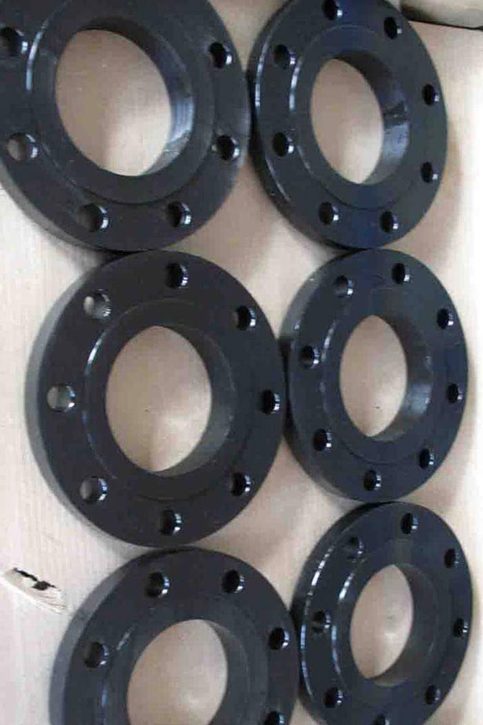
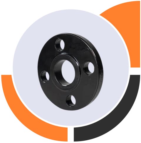
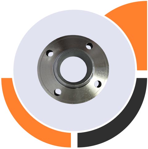
Types of Flanges
Threaded / Screwed / Forged / Plate
Class / Pressure
150#, 300#, 600#, 900#, 1500#, 2500#, PN6, PN10, PN16, PN25, PN40, PN64 etc.

Flange Face Type
Flate Face (FF), Raised Face (RF), Ring Type Joint (RTJ)
Flanges Process
Forging, Rolling, Casting
Flange Thread
FNPT, NPT, BSPT, MNPT, BSPP


Plate

Shear

Press

Inspection

Lathe

Drilling

Cleaning

Flange

Inspection

Analytic

Marking

Packing & Shipping